Air-source heat pump boiler (ASHPB)
The ASHPB family pairs the shared refrigerant cycle with an
outdoor-coil source side and a DHW tank sink side. This is the
validated reference example used by the Getting Started flow.
Overview
ASHPB solves the closed refrigerant cycle every step against an
outdoor coil (ε-NTU air-side) and a tank-coupled condenser. The
class is tmhp.AirSourceHeatPumpBoiler. Three composed
variants extend it with subsystems:
tmhp.ASHPB_STC_preheat— STC heats the mains feed before it reaches the tank.tmhp.ASHPB_STC_tank— STC charges a separate top node of a stratified tank.tmhp.ASHPB_PV_ESS— PV generation + battery storage routes electricity to the compressor and auxiliaries before drawing grid.
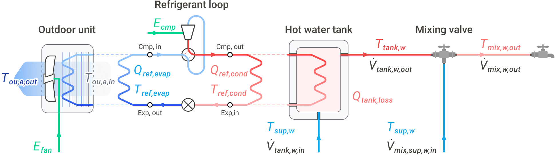
Reference ASHPB instantiation. This physical wiring view is useful for the validated air-source DHW case, while the shared compressor / expander / heat-exchanger cycle core is reused by the other TMHP source and demand-side families.
Base usage
from tmhp import AirSourceHeatPumpBoiler

ashpb = AirSourceHeatPumpBoiler(ref="R32")

# Steady-state snapshot
result = ashpb.analyze_steady(
    T_tank_w=55.0,    # tank water [°C]
    T0=7.0,           # outdoor air [°C]
    Q_ref_tank=8_000, # target condenser duty [W]
)

# Time-stepping dynamic run — see Getting Started for full schedule
# construction.
# df = ashpb.analyze_dynamic(...)
Default compressor efficiencies
A bare AirSourceHeatPumpBoiler uses the paper-validated compressor
relations below, where r_p is pressure ratio and rps is compressor
speed in revolutions per second:
volumetric:
1.0 - 0.020 * (r_p - 1.0)isentropic:
0.90 - 0.02 * r_pcombined electromechanical:
0.80 - 3.0e-5 * (rps - 55.0) ** 2
An explicitly supplied float or callable for the corresponding constructor argument overrides these defaults.
Source-side mechanics
ASHPB models its outdoor coil as a variable-speed fan coupled to an ε-NTU heat exchanger. Fan electrical power follows an ASHRAE 90.1-style cubic-with-speed curve; coil ε is recomputed each step from the resolved refrigerant mass flow.
Sink-side mechanics
The sink is a single-node DHW tank (with optional stratification on
the _STC_tank variant). The tank energy balance is solved
implicitly per step with fsolve, jointly with the refrigerant
cycle.
Composed variants
The standalone ASHPB: outdoor coil ε-NTU evaporator, R32 cycle, DHW tank charge.
from tmhp import AirSourceHeatPumpBoiler

ashpb = AirSourceHeatPumpBoiler(ref="R32")
result = ashpb.analyze_steady(
    T_tank_w=55.0,
    T0=7.0,
    Q_ref_tank=8_000,
)
Adds a flat-plate STC that preheats mains water entering the tank. Reduces the tank-charge duty the heat pump has to deliver.
from tmhp import ASHPB_STC_preheat
from tmhp.subsystems import SolarThermalCollector

stc = SolarThermalCollector(A_stc=4.0, stc_tilt=35.0, stc_azimuth=180.0)
model = ASHPB_STC_preheat(stc=stc, ref="R32")
STC charges a separate top node of a stratified tank; the heat pump charges the bottom. Top-of-tank water is drawn first.
from tmhp import ASHPB_STC_tank
from tmhp.subsystems import SolarThermalCollector

stc = SolarThermalCollector(A_stc=4.0, stc_tilt=35.0, stc_azimuth=180.0)
model = ASHPB_STC_tank(stc=stc, ref="R32")
Photovoltaic generation + ESS preferentially feeds the compressor and auxiliaries.
from tmhp import ASHPB_PV_ESS
from tmhp.subsystems import EnergyStorageSystem, PhotovoltaicSystem

model = ASHPB_PV_ESS(
    pv=PhotovoltaicSystem(),
    ess=EnergyStorageSystem(),
    ref="R32",
)
STC preheat
A SolarThermalCollector heats the cold mains
water before it reaches the DHW tank, so the heat pump sees pre-heated
water during the preheat window.
import numpy as np

from tmhp import ASHPB_STC_preheat
from tmhp.subsystems import SolarThermalCollector

stc = SolarThermalCollector(
    A_stc=4.0,             # 4 m² collector area
    stc_tilt=35.0,
    stc_azimuth=180.0,
)

model = ASHPB_STC_preheat(stc=stc, ref="R32")
Drive it the same way as base ASHPB, adding irradiance schedules
(I_DN_schedule, I_dH_schedule) — both in W/m² per step:
dt_s          = 60
n_steps       = 24 * 3600 // dt_s
hour_of_day   = np.arange(n_steps) / 60.0

# Crude clear-sky irradiance: bell from 06:00 to 18:00.
day_window    = (hour_of_day >= 6.0) & (hour_of_day <= 18.0)
sun_shape     = np.sin(np.pi * (hour_of_day - 6.0) / 12.0)
I_DN          = np.where(day_window, 800.0 * sun_shape, 0.0)
I_dH          = np.where(day_window, 100.0 * sun_shape, 0.0)

T0  = np.full(n_steps, 5.0)
dhw = np.zeros(n_steps)

df = model.analyze_dynamic(
    simulation_period_sec = n_steps * dt_s,
    dt_s                  = dt_s,
    T_tank_w_init_C       = 50.0,
    dhw_usage_schedule    = dhw,
    T0_schedule           = T0,
    I_DN_schedule         = I_DN,
    I_dH_schedule         = I_dH,
)
To quantify the contribution, run the same schedules through a base
AirSourceHeatPumpBoiler and difference the daily compressor
energy:
from tmhp import AirSourceHeatPumpBoiler

base = AirSourceHeatPumpBoiler(ref="R32").analyze_dynamic(
    simulation_period_sec = n_steps * dt_s,
    dt_s                  = dt_s,
    T_tank_w_init_C       = 50.0,
    dhw_usage_schedule    = dhw,
    T0_schedule           = T0,
)

def daily_kwh(s, dt_s=dt_s):
    return float(s.sum()) * dt_s / 3.6e6

saving = daily_kwh(base["E_cmp [W]"]) - daily_kwh(df["E_cmp [W]"])
print(f"STC preheat saving: {saving:.2f} kWh/day")
- class tmhp.ASHPB_STC_preheat(*, stc, **kwargs)[source]
Bases:
AirSourceHeatPumpBoilerASHPB + SolarThermalCollector in mains_preheat placement.
Physical configuration
The STC preheats mains cold water before it enters the storage tank. The raised inlet temperature (
T_tank_w_in_override_K) reduces the thermal load on the heat pump compressor.Orchestration responsibility
This class owns all simulation logic for the STC:
_run_subsystems: activation probe +calc_performance()→ setsT_tank_w_in_override_Kwhen active_augment_results: result column assembly (uses pump outlet temperature directly; no re-evaluation at solved tank temp)_postprocess: STC exergy calculation. Tank boundary corrections are not applied because the preheated inlet temperature is already reflected in the coreX_tank_w_in [W]column (X_in_tank_add = 0).
- type stc:
- param stc:
Pure physics engine. No
modeconstraint required.- type stc:
SolarThermalCollector
- type **kwargs:
- param **kwargs:
Forwarded to
AirSourceHeatPumpBoiler.- raises TypeError:
If stc is not a
SolarThermalCollectorinstance.
- __init__(*, stc, **kwargs)[source]
- Parameters:
stc (
SolarThermalCollector)
STC with stratified tank
- class tmhp.ASHPB_STC_tank(*, stc, **kwargs)[source]
Bases:
AirSourceHeatPumpBoilerASHPB + SolarThermalCollector in tank_circuit placement.
Physical configuration
The STC collector loop is connected directly to the storage tank. The STC draws water from the tank, heats it via solar energy, and returns it through the pump. The STC is activated only when the collector’s thermal gain exceeds the pump electricity required to circulate the loop.
Orchestration responsibility
This class owns all simulation logic for the STC:
_run_subsystems: activation probe +calc_performance()_augment_results: result column assembly (re-evaluates at solved tank temperature for accuracy)_postprocess: STC exergy calculation and tank boundary correction (X_tot,Xc_tank)
- type stc:
- param stc:
Pure physics engine. No
modeconstraint required.- type stc:
SolarThermalCollector
- type **kwargs:
- param **kwargs:
Forwarded to
AirSourceHeatPumpBoiler.- raises TypeError:
If stc is not a
SolarThermalCollectorinstance.
- T_stc_max_C: float = 100.0
Boiling-protection ceiling [°C]. The STC loop must not circulate when the probed collector outlet would reach/exceed this temperature (liquid water boiling at 1 atm). Prevents non-physical >100 °C circulation and the associated phantom gain when the tank is near saturation.
- __init__(*, stc, **kwargs)[source]
- Parameters:
stc (
SolarThermalCollector)
PV + ESS
PhotovoltaicSystem generation feeds the
compressor and auxiliaries; an EnergyStorageSystem
buffers midday surplus for evening load; grid import covers
whatever the two cannot supply.
from tmhp import ASHPB_PV_ESS
from tmhp.subsystems import EnergyStorageSystem, PhotovoltaicSystem

model = ASHPB_PV_ESS(
    pv  = PhotovoltaicSystem(),
    ess = EnergyStorageSystem(),
    ref = "R32",
)

# Pass I_DN_schedule + I_dH_schedule to analyze_dynamic exactly
# as you would for ASHPB_STC_preheat.
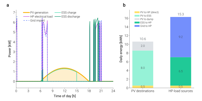
24-hour ASHPB_PV_ESS run with a clear-sky irradiance profile
and default PhotovoltaicSystem / EnergyStorageSystem sizes.
Panel (b) makes the sizing tradeoff readable: shrinking the ESS
column on the left would push more of the right-hand bar from
“PV” to “Grid”. Generated by
scripts/visualization/pv_ess_energy_balance.py.
- class tmhp.ASHPB_PV_ESS(*, pv, ess=None, eta_inv=0.95, T_inv_K=313.15, **kwargs)[source]
Bases:
AirSourceHeatPumpBoilerASHPB scenario where the heat pump is supplied by PV + ESS + Grid.
The PV/ESS routing is resolved synchronously inside
_augment_resultsafter the HP compressor load is known. No 1-step lag: the PV energy is allocated to the exact HP load produced in the same timestep.- Parameters:
pv (PhotovoltaicSystem) – Pure-physics PV + charge-controller model.
ess (EnergyStorageSystem) – Pure-physics battery model with
charge()/discharge().eta_inv (float) – Inverter DC→AC efficiency [–].
T_inv_K (float) – Inverter temperature for entropy calculation [K].
**kwargs – Forwarded to
AirSourceHeatPumpBoiler.
- __init__(*, pv, ess=None, eta_inv=0.95, T_inv_K=313.15, **kwargs)[source]
- Parameters:
pv (
PhotovoltaicSystem)ess (
Optional[EnergyStorageSystem])eta_inv (
float)T_inv_K (
float)
API reference
Integrated System Model: Air Source Heat Pump Boiler (ASHPB).
This system class orchestrates the dynamic interaction between distinct thermodynamic sub-components to simulate the overall heating performance. While implemented as an integrated model, its physical calculations represent the behavior of:
Refrigerant Cycle (Vapor-Compression): Evaluates thermodynamic states using CoolProp, enforcing superheat/subcool margins.
Heat Pump Compressor: Models the compression process using isentropic and volumetric efficiencies to compute the actual discharge enthalpy and mass flow rate. The compressor power is determined from the enthalpy difference and the mass flow rate.
Expansion Valve: Modeled as an isenthalpic expansion device (constant enthalpy) that throttles the refrigerant from the condensing pressure down to the evaporating pressure.
Heat Exchangers (Condenser & Evaporator):
Condenser: Placed inside the tank (hydronic), utilizing a static overall heat transfer coefficient (UA_tank_hx).
Evaporator: Air-coupled outdoor unit, utilizing a dynamic overall heat transfer coefficient (UA_ou) that scales non-linearly with fan airflow (Colburn j-factor analogy).
Thermal Storage Tank: Modeled with lumped-capacitance and DHW mixing logic.
At each time step, the model finds the minimum-power operating point (compressor + fan) via bounded 1-D optimisation (Brent’s method) over the evaporator approach temperature difference.
Note
See the project paper (KJACR 2025) for the underlying refrigerant-cycle theory and component-level modelling assumptions of this system.
Optional sub-components (injected via constructor):
- SolarThermalCollector — tank-circuit or mains-preheat placement
- (future) PVPanel — photovoltaic integration
Tank-level management and UV disinfection are built-in features configured through constructor parameters.
- class tmhp.air_source_heat_pump_boiler.AirSourceHeatPumpBoiler(ref='R134a', V_cmp_ref=None, eta_cmp_isen=None, eta_cmp_vol=None, eta_cmp=None, dT_superheat=5.0, dT_subcool=5.0, UA_tank_hx=None, UA_ou_rated=None, n_ou=0.65, dV_fan_a_rated=None, dP_fan_rated=None, A_cross=None, eta_fan_rated=None, T_tank_w_upper_bound=65.0, T_tank_w_lower_bound=60.0, T_mix_w_out=40.0, T_sup_w=15.0, hp_capacity=15000.0, dV_mix_w_out_max=0.0045, r0=0.2, H=1.2, x_shell=0.005, x_ins=0.05, k_shell=25, k_ins=0.03, h_o=15, tank_always_full=True, tank_level_lower_bound=0.5, tank_level_upper_bound=1.0, dV_tank_w_in_refill=0.001, prevent_simultaneous_flow=False, hp_on_schedule=None, stc=None, pv=None, uv=None, vsd_coeffs=None, T_sur=20.0, dT_hx_min=0.5, PR_cycle_min=1.5, PR_cycle_max=20.0, rps_min=10.0, rps_max=150.0, V_disp_cmp=None, eta_cmp_electro_mech=None, UA_tank=None, UA_cond_design=None, UA_evap_design=None, dV_ou_fan_a_design=None, dP_ou_fan_design=None, A_cross_ou=None, eta_ou_fan_design=None, vsd_coeffs_ou=None)[source]
Bases:
objectAir source heat pump boiler with outdoor-air evaporator.
The refrigerant cycle is resolved via CoolProp with user-specified superheat / subcool margins. The condenser approach temperature is determined analytically (
dT_ref_tank = Q_ref_tank / UA_tank_hx), and a bounded 1-D optimiser (Brent’s method) minimises total electrical input (E_cmp + E_ou_fan) over the evaporator approach.Unless explicitly injected, compressor efficiencies use the paper-validated relations
eta_cmp_vol = 1.0 - 0.020 * (r_p - 1.0),eta_cmp_isen = 0.90 - 0.02 * r_p, andeta_cmp = 0.80 - 3.0e-5 * (rps - 55.0) ** 2.- Parameters:
ref (
str)V_cmp_ref (
Optional[float])eta_cmp_isen (
Union[float,Callable,None])eta_cmp_vol (
Union[float,Callable,None])eta_cmp (
Union[float,Callable,None])dT_superheat (
float)dT_subcool (
float)UA_tank_hx (
Optional[float])UA_ou_rated (
Optional[float])n_ou (
float)dV_fan_a_rated (
Optional[float])dP_fan_rated (
Optional[float])A_cross (
Optional[float])eta_fan_rated (
Optional[float])T_tank_w_upper_bound (
float)T_tank_w_lower_bound (
float)T_mix_w_out (
float)T_sup_w (
float)hp_capacity (
float)dV_mix_w_out_max (
float)r0 (
float)H (
float)x_shell (
float)x_ins (
float)k_shell (
float)k_ins (
float)h_o (
float)tank_always_full (
bool)tank_level_lower_bound (
float)tank_level_upper_bound (
float)dV_tank_w_in_refill (
float)prevent_simultaneous_flow (
bool)hp_on_schedule (
Optional[list[tuple[float,float]]])stc (
Optional[SolarThermalCollector])pv (
Optional[PhotovoltaicSystem])vsd_coeffs (
Optional[dict])T_sur (
float)dT_hx_min (
float)PR_cycle_min (
float)PR_cycle_max (
float)rps_min (
float)rps_max (
float)V_disp_cmp (
Optional[float])eta_cmp_electro_mech (
Union[float,Callable,None])UA_tank (
Optional[float])UA_cond_design (
Optional[float])UA_evap_design (
Optional[float])dV_ou_fan_a_design (
Optional[float])dP_ou_fan_design (
Optional[float])A_cross_ou (
Optional[float])eta_ou_fan_design (
Optional[float])vsd_coeffs_ou (
Optional[dict])
- __init__(ref='R134a', V_cmp_ref=None, eta_cmp_isen=None, eta_cmp_vol=None, eta_cmp=None, dT_superheat=5.0, dT_subcool=5.0, UA_tank_hx=None, UA_ou_rated=None, n_ou=0.65, dV_fan_a_rated=None, dP_fan_rated=None, A_cross=None, eta_fan_rated=None, T_tank_w_upper_bound=65.0, T_tank_w_lower_bound=60.0, T_mix_w_out=40.0, T_sup_w=15.0, hp_capacity=15000.0, dV_mix_w_out_max=0.0045, r0=0.2, H=1.2, x_shell=0.005, x_ins=0.05, k_shell=25, k_ins=0.03, h_o=15, tank_always_full=True, tank_level_lower_bound=0.5, tank_level_upper_bound=1.0, dV_tank_w_in_refill=0.001, prevent_simultaneous_flow=False, hp_on_schedule=None, stc=None, pv=None, uv=None, vsd_coeffs=None, T_sur=20.0, dT_hx_min=0.5, PR_cycle_min=1.5, PR_cycle_max=20.0, rps_min=10.0, rps_max=150.0, V_disp_cmp=None, eta_cmp_electro_mech=None, UA_tank=None, UA_cond_design=None, UA_evap_design=None, dV_ou_fan_a_design=None, dP_ou_fan_design=None, A_cross_ou=None, eta_ou_fan_design=None, vsd_coeffs_ou=None)[source]
- Parameters:
ref (
str)V_cmp_ref (
Optional[float])eta_cmp_isen (
Union[float,Callable,None])eta_cmp_vol (
Union[float,Callable,None])eta_cmp (
Union[float,Callable,None])dT_superheat (
float)dT_subcool (
float)UA_tank_hx (
Optional[float])UA_ou_rated (
Optional[float])n_ou (
float)dV_fan_a_rated (
Optional[float])dP_fan_rated (
Optional[float])A_cross (
Optional[float])eta_fan_rated (
Optional[float])T_tank_w_upper_bound (
float)T_tank_w_lower_bound (
float)T_mix_w_out (
float)T_sup_w (
float)hp_capacity (
float)dV_mix_w_out_max (
float)r0 (
float)H (
float)x_shell (
float)x_ins (
float)k_shell (
float)k_ins (
float)h_o (
float)tank_always_full (
bool)tank_level_lower_bound (
float)tank_level_upper_bound (
float)dV_tank_w_in_refill (
float)prevent_simultaneous_flow (
bool)hp_on_schedule (
Optional[list[tuple[float,float]]])stc (
Optional[SolarThermalCollector])pv (
Optional[PhotovoltaicSystem])vsd_coeffs (
Optional[dict])T_sur (
float)dT_hx_min (
float)PR_cycle_min (
float)PR_cycle_max (
float)rps_min (
float)rps_max (
float)V_disp_cmp (
Optional[float])eta_cmp_electro_mech (
Union[float,Callable,None])UA_tank (
Optional[float])UA_cond_design (
Optional[float])UA_evap_design (
Optional[float])dV_ou_fan_a_design (
Optional[float])dP_ou_fan_design (
Optional[float])A_cross_ou (
Optional[float])eta_ou_fan_design (
Optional[float])vsd_coeffs_ou (
Optional[dict])
- analyze_steady(T_tank_w, T0, Q_ref_tank, *, return_dict=True)[source]
Run a steady-state performance snapshot.
Evaluates the refrigerant cycle at a given operating point (T_tank_w, T0, Q_ref_tank) without solving the tank energy balance or tracking dynamic flows.
- Parameters:
T_tank_w (float) – Tank water temperature [°C] — treated as a given input.
T0 (float) – Dead-state / outdoor-air temperature [°C].
Q_ref_tank (float) – Target condenser heat rate [W].
return_dict (bool) – If True return dict; else single-row DataFrame.
- Returns:
Cycle state plus diagnostic flags.
Two keys are useful for branching:
"converged"(bool) — True only when the HX optimisation and the SciPy optimiser both succeeded."failure_reason"(str) — one of"none","cycle_invalid","hx_not_converged", or"optimizer_failed".
ASHPB returns the cycle numbers (
E_cmp,Q_ref_tank, …) whenever_calc_stateproduced a dict at all. Afailure_reasonof"hx_not_converged"therefore does not invalidate the result: it only means the HX residual exceeded tolerance and the converged flag is False. Off-mode fallback (E_cmp=0) only occurs when the cycle itself was infeasible.- Return type:
dict | pd.DataFrame
- make_initial_state(T_tank_w_init_C, tank_level_init=1.0)[source]
Build the initial carried state for a
step()-driven run.- Parameters:
T_tank_w_init_C (
float)tank_level_init (
float)
- Return type:
DynamicState
- step(state, inputs, dt_s)[source]
Advance one timestep from state under inputs.
Returns
(new_state, result_row). Re-entrant: every cross-step quantity is read fromstate(neverself), so an external co-simulation master (FMI/EnergyPlus) can drive the model one exchange at a time and re-run it independently. The per-step environment is set onselfafresh frominputseach call (transient scratch shared with the cycle/tank helpers).- Parameters:
state (DynamicState) – Carried state from
make_initial_stateor the previousstep.inputs (dict) – Per-step drivers:
n(int),current_time_s[s],T0[°C],dV_mix_w_out[m³/s],T_sup_w[°C],T_sur[°C], and optionalI_DN/I_dH[W/m²] (default 0).dt_s (float) – Timestep [s].
- Return type:
tuple[DynamicState,dict]
- analyze_dynamic(simulation_period_sec, dt_s, T_tank_w_init_C, dhw_usage_schedule, T0_schedule, I_DN_schedule=None, I_dH_schedule=None, T_sup_w_schedule=None, tank_level_init=1.0, result_save_csv_path=None, T_sur_schedule=None)[source]
Run a time-stepping dynamic simulation.
Fully implicit scheme:
fsolvesolves for[T_next, level_next]each timestep.- Parameters:
simulation_period_sec (int) – Total simulation duration [s].
dt_s (int) – Time step size [s].
T_tank_w_init_C (float) – Initial tank temperature [°C].
dhw_usage_schedule (np.ndarray) – DHW volumetric flow rate per step [m³/s].
T0_schedule (array-like) – Outdoor temperature per step [°C].
I_DN_schedule (array-like | None) – Direct-normal irradiance per step [W/m²].
I_dH_schedule (array-like | None) – Diffuse-horizontal irradiance [W/m²].
T_sup_w_schedule (array-like | None) – Mains water supply temperature per step [°C]. If
None, the constructor valueT_sup_wis used for every step (backward-compatible).tank_level_init (float) – Initial fractional tank level (0–1).
result_save_csv_path (str | None) – Optional CSV output path.
- Returns:
Per-timestep result DataFrame.
- Return type:
pd.DataFrame
- postprocess_exergy(df)[source]
Compute ASHP-specific exergy variables.
Owns the full HP exergy topology:
Refrigerant state-point exergy (CoolProp)
Electricity = exergy (compressor, OU fan, UV)
Air exergy (outdoor unit)
Heat exchanger Carnot exergy (condenser, evaporator)
Water exergy (tank inlet/outlet, mixing valve)
Heat loss exergy, tank stored exergy
Subsystem exergy via
calc_exergy()protocolComponent-level exergy destruction
Exergetic efficiency metrics
- Parameters:
df (pd.DataFrame) – Result DataFrame from
analyze_dynamic().- Returns:
DataFrame with exergy columns appended.
- Return type:
pd.DataFrame
ASHPB with SolarThermalCollector — mains_preheat placement.
Phase 3 restructuring: all simulation orchestration logic
(activation probe, result assembly, exergy calculation) is
implemented directly in this class. SolarThermalCollector
is used purely as a physics engine (calc_performance()),
with no dependency on step(), assemble_results(), or
calc_exergy().
Note
See the project paper for the orchestration logic and energy/exergy boundaries used by hybrid (STC + HP) systems.
Usage
from enex_analysis import SolarThermalCollector
from enex_analysis.ASHPB_STC_preheat import ASHPB_STC_preheat

stc = SolarThermalCollector(A_stc=4.0)
model = ASHPB_STC_preheat(
    stc=stc,
    ref="R134a",
    hp_capacity=15_000.0,
    T_tank_w_lower_bound=55.0,
    T_tank_w_upper_bound=65.0,
    T_mix_w_out=42.0,
)
df = model.analyze_dynamic(...)
- class tmhp.ashpb_stc_preheat.ASHPB_STC_preheat(*, stc, **kwargs)[source]
Bases:
AirSourceHeatPumpBoilerASHPB + SolarThermalCollector in mains_preheat placement.
Physical configuration
The STC preheats mains cold water before it enters the storage tank. The raised inlet temperature (
T_tank_w_in_override_K) reduces the thermal load on the heat pump compressor.Orchestration responsibility
This class owns all simulation logic for the STC:
_run_subsystems: activation probe +calc_performance()→ setsT_tank_w_in_override_Kwhen active_augment_results: result column assembly (uses pump outlet temperature directly; no re-evaluation at solved tank temp)_postprocess: STC exergy calculation. Tank boundary corrections are not applied because the preheated inlet temperature is already reflected in the coreX_tank_w_in [W]column (X_in_tank_add = 0).
- type stc:
- param stc:
Pure physics engine. No
modeconstraint required.- type stc:
SolarThermalCollector
- type **kwargs:
- param **kwargs:
Forwarded to
AirSourceHeatPumpBoiler.- raises TypeError:
If stc is not a
SolarThermalCollectorinstance.
- __init__(*, stc, **kwargs)[source]
- Parameters:
stc (
SolarThermalCollector)
ASHPB with SolarThermalCollector — tank_circuit placement.
Phase 3 restructuring: all simulation orchestration logic
(activation probe, result assembly, exergy calculation) is
implemented directly in this class. SolarThermalCollector
is used purely as a physics engine (calc_performance()),
with no dependency on step(), assemble_results(), or
calc_exergy().
Note
See the project paper for the orchestration logic and energy/exergy boundaries used by hybrid (STC + HP, stratified tank) systems.
Usage
from enex_analysis import SolarThermalCollector
from enex_analysis.ASHPB_STC_tank import ASHPB_STC_tank

stc = SolarThermalCollector(A_stc=4.0)
model = ASHPB_STC_tank(
    stc=stc,
    ref="R134a",
    hp_capacity=15_000.0,
    T_tank_w_lower_bound=55.0,
    T_tank_w_upper_bound=65.0,
    T_mix_w_out=42.0,
)
df = model.analyze_dynamic(...)
- class tmhp.ashpb_stc_tank.ASHPB_STC_tank(*, stc, **kwargs)[source]
Bases:
AirSourceHeatPumpBoilerASHPB + SolarThermalCollector in tank_circuit placement.
Physical configuration
The STC collector loop is connected directly to the storage tank. The STC draws water from the tank, heats it via solar energy, and returns it through the pump. The STC is activated only when the collector’s thermal gain exceeds the pump electricity required to circulate the loop.
Orchestration responsibility
This class owns all simulation logic for the STC:
_run_subsystems: activation probe +calc_performance()_augment_results: result column assembly (re-evaluates at solved tank temperature for accuracy)_postprocess: STC exergy calculation and tank boundary correction (X_tot,Xc_tank)
- type stc:
- param stc:
Pure physics engine. No
modeconstraint required.- type stc:
SolarThermalCollector
- type **kwargs:
- param **kwargs:
Forwarded to
AirSourceHeatPumpBoiler.- raises TypeError:
If stc is not a
SolarThermalCollectorinstance.
- T_stc_max_C: float = 100.0
Boiling-protection ceiling [°C]. The STC loop must not circulate when the probed collector outlet would reach/exceed this temperature (liquid water boiling at 1 atm). Prevents non-physical >100 °C circulation and the associated phantom gain when the tank is near saturation.
- __init__(*, stc, **kwargs)[source]
- Parameters:
stc (
SolarThermalCollector)
- stc: SolarThermalCollector | None
- ref: str
- V_cmp_ref: float
- eta_cmp_isen: float | Callable
- eta_cmp_vol: float | Callable
- eta_cmp: float | Callable
- dT_superheat: float
- dT_subcool: float
- dT_hx_min: float
- PR_cycle_min: float
- PR_cycle_max: float
- rps_min: float
- rps_max: float
- hp_capacity: float
- n_ou: float
- dP_fan_rated: float
- eta_fan_rated: float
- E_fan_rated: float
- vsd_coeffs: dict
- fan_params: dict
- tank_physical: dict
- UA_tank_wall: float
- T_sur_K: float
- V_tank_full: float
- C_tank: float
- dV_mix_w_out_max: float
- T_tank_w_upper_bound: float
- T_tank_w_lower_bound: float
- T_sup_w: float
- T_sup_w_K: float
- T_tank_w_in: float
- T_mix_w_out: float
- T_tank_w_in_K: float
- T_mix_w_out_K: float
- tank_always_full: bool
- tank_level_lower_bound: float
- tank_level_upper_bound: float
- dV_tank_w_in_refill: float
- prevent_simultaneous_flow: bool
- hp_on_schedule: list[tuple[float, float]]
- pv: PhotovoltaicSystem | None
- dV_tank_w_in: float
- dV_tank_w_out: float
- dV_mix_sup_w_in: float
- dV_mix_w_out: float
ASHPB Scenario: Heat Pump driven by PV + ESS with Grid/Dump integration.
Energy routing (all logic lives here, subsystems are pure physics):
PV generation →
pv.calc_performance()DC routing: - PV surplus →
ess.charge(); leftover → dump - PV deficit →ess.discharge(); leftover → grid importInverter conversion loss applied to DC supply
Grid import covers any remaining AC shortfall
Note
See the project paper for the orchestration logic and energy/exergy boundaries used by hybrid (PV + ESS + HP) systems.
- class tmhp.ashpb_pv_ess.ASHPB_PV_ESS(*, pv, ess=None, eta_inv=0.95, T_inv_K=313.15, **kwargs)[source]
Bases:
AirSourceHeatPumpBoilerASHPB scenario where the heat pump is supplied by PV + ESS + Grid.
The PV/ESS routing is resolved synchronously inside
_augment_resultsafter the HP compressor load is known. No 1-step lag: the PV energy is allocated to the exact HP load produced in the same timestep.- Parameters:
pv (PhotovoltaicSystem) – Pure-physics PV + charge-controller model.
ess (EnergyStorageSystem) – Pure-physics battery model with
charge()/discharge().eta_inv (float) – Inverter DC→AC efficiency [–].
T_inv_K (float) – Inverter temperature for entropy calculation [K].
**kwargs – Forwarded to
AirSourceHeatPumpBoiler.
- __init__(*, pv, ess=None, eta_inv=0.95, T_inv_K=313.15, **kwargs)[source]
- Parameters:
pv (
PhotovoltaicSystem)ess (
Optional[EnergyStorageSystem])eta_inv (
float)T_inv_K (
float)
Validation
ASHPB has been benchmarked against the Samsung EHS Mono HT Quiet R32 14 kW catalogue across 15 operating points. See Validation for the parity plot and per-point comparison.